The drive is doing what the control. Sizing calculations of Boiler Pumps and ID FD Fans.
Fan Calculator Axial Centrifugal Pressure Flow Calqlata
As main fans for mine ventilation systems while the axial type is favoured for underground locations.

. However if you were to have an ID fan on the back end of the furnace while it would be expensive based on the exotic materials would the impeller etc be that diffenrent in design. Fan Life Testing. Static Pressure vs Fan speed CTC Design Inc.
Fig 2 shows the pressures through a fan each of which is described below. This will give you the air flow in CFM or cubic feet per minute. Radial fans are industrial workhorses because of their high static pressures upto 1400 mm WC and ability to handle heavily contaminated airstreams.
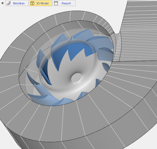
The primary control is for furnace pressure on a boiler. A method is presented for redesigning a centrifugal impeller and its inlet duct. The Induced Draft ID fans and Forced Draft FD fans provide control for draft and forced air zoning of fuel burned furnaces of steam generation plant of a thermal power plant.
In not very big combustors natural draft the air induced by the difference of density with the hot gas is not enough to sustain combustion and you need fans. Answer 1 of 5. Static pressure characteristics and the pressure loss of.
Determine the air flow. Induced Draft ID Fan is used to draw the flue gases from the system generated from the combustion of fuel. Sample sizing calculations for BFW pumps and Fans for a typical Coal fired Boiler generating steam of 50000 Kghr at 67 kgcm2 and 485.
ID Fan Design Calculations- Equations. Books On Idfd Fan Design Calculations - posted in Industrial Professionals. 9 to 16 blades of airfoil curved away from the direction of rotation.
Effect of axial gap between inlet nozzle and impeller on efficiency and flow pattern in centrifugal fans numerical and experimental analysis. About Steam boiler steam and drawing thermodynamics steam table Know about some things Boiler Math solution Energy conservation thermodynamic therma. The ID fan problems have arisen from the bearing lubrication system which provides oil recirculation to the induction motor bearings and fan main shaft bearings.
Fan Data RPM Motor Sheave Dia Fan Calculation authored and generated by CTC Design Inc. The fan efficiency is the ratio between power transferred to airflow and the power used by the fan. The fan efficiency is in general independent of the air density and can be expressed as.
Online Induced Draft ID Fan Motor Power Calculator. Is the static pressure on the inlet side of the fanThis should also include the velocity pressure on the. Fans are in parallel.
Safety FactorSelecting a fan Select a fan using the required air flow. Suitable for higher static pressure up to 14 35 KPa. NMB uses parametric failure modes during life testing to calculate for life expectancy.
An axial fan is a type of fan that causes gas to flow through it in an axial direction parallel to the shaft about which the blades rotate. Motor power required for. Let us assume Fan efficiency as 75 and.
Power requirements of FD Fan. Therefore FD fan rating is 15 m3s of air at 230 mm WC static head. We are controlling fan speed with a variable frequency drive.
So FD fan head should be about 230 mm of WC. Performance Calculations 8 Fan Control 10 Fan Systems 11 Fan Selection Procedure 12 Process Data Sheet 15 APPENDIX A 16 APPENDIX B 18 APPENDIX C 20 APPENDIX D 22 APPENDIX E. Please do suggest on the same.
Now that you know the fan area it is time to multiply it by the air speed of the fan. In this chapter we shall define fan pressures and examine some of the basic theory. The air flow of a mounted fan can be found from the fans air flow vs.
The sweet spot is when the inlet diameter of. The flow is axial at entry and exit. The double-discharge volute casing is a structural constraint and is maintained for its shape.
Life expectancy of a cooling fan is a critical element in thermal design. Because of their simple design radial. The highest speed of the centrifugal fans.
Fan Testing Services.

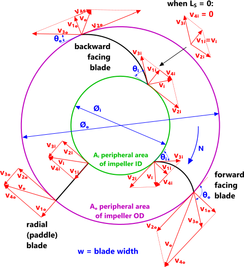
Figure 1 From A Digital Design Method Of Geometric Model For Centrifugal Fan Impeller Based On Solidworks And Vb Semantic Scholar

Oem Replacement Impellers Continental Fan Industrial Fan Rapid Prototyping Dust Collector
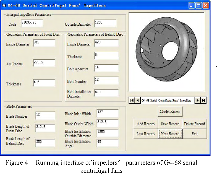
Figure 4 From A Digital Design Method Of Geometric Model For Centrifugal Fan Impeller Based On Solidworks And Vb Semantic Scholar

Sugar Technology International Sugar Industry Tandem Milling
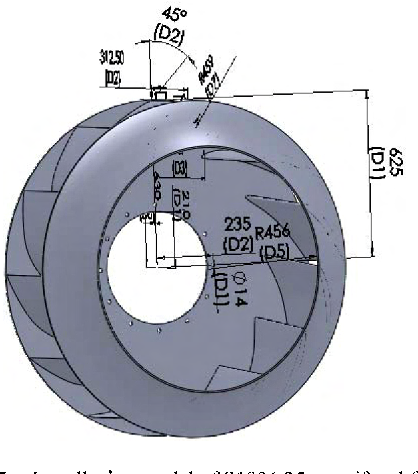
Figure 4 From A Digital Design Method Of Geometric Model For Centrifugal Fan Impeller Based On Solidworks And Vb Semantic Scholar
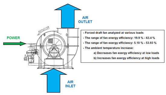
Jmse Free Full Text Energy And Exergy Analyses Of Forced Draft Fan For Marine Steam Propulsion System During Load Change Html
Jmse Free Full Text Energy And Exergy Analyses Of Forced Draft Fan For Marine Steam Propulsion System During Load Change Html
Software For The Design Of Fans Blowers
0 comments
Post a Comment